Inductance and Coils: Theory and Practice
💡 Quick Tip
Key Concept: Coils oppose sudden changes in current by storing energy in a magnetic field.
Understanding Inductance
Inductance (L) is the physical property of an electrical circuit that quantifies its ability to oppose changes in the electric current flowing through it. This opposition manifests as the generation of an electromotive force (EMF) in the opposite direction of the change. The component that maximizes this effect is the coil (or inductor), which consists of a conductive wire wound into a series of loops.
Fundamental Physical Laws
The operation of coils is governed by two primary laws:
- Faraday's Law: States that a change in magnetic flux through a circuit induces a voltage in that circuit.
- Lenz's Law: Dictates that the direction of the induced voltage is such that it opposes the cause (the change in current) that produced it. Mathematically, the induced voltage is $V = L cdot (di/dt)$. This implies that if current is cut off abruptly (high $di/dt$), the coil will generate a massive voltage spike to attempt to maintain the current flow.
Factors Influencing Inductance
- Number of Turns: Inductance increases with the square of the number of wire loops.
- Core Material: Using a ferromagnetic core (like ferrite or iron) multiplies the inductance by concentrating the magnetic field lines.
- Geometry: The diameter, length, and winding density of the coil also determine the final value, measured in Henries (H).
Technical Applications
Inductors are vital for signal filtering (blocking high-frequency noise while allowing DC to pass), transformer construction, electric motors, and resonant circuits for radio frequency (RF) tuning.
📊 Practical Example
Real-World Scenario: Eliminating Noise in a Industrial Data Line
Imagine an industrial control system where a sensitive data cable runs near a powerful electric motor. The motor creates electromagnetic interference (EMI) that corrupts the data packets. We will solve this using a common-mode choke (often seen as a plastic cylinder on USB cables).
Step 1: Identifying the Noise. The interference appears as high-frequency pulses "riding" on top of the useful low-frequency signal.
Step 2: Selecting the Ferrite. We use a ferrite bead or core. Ferrites exhibit high impedance to high frequencies, converting the noise into a tiny amount of heat, while allowing the lower-frequency data signal to pass through unaffected.
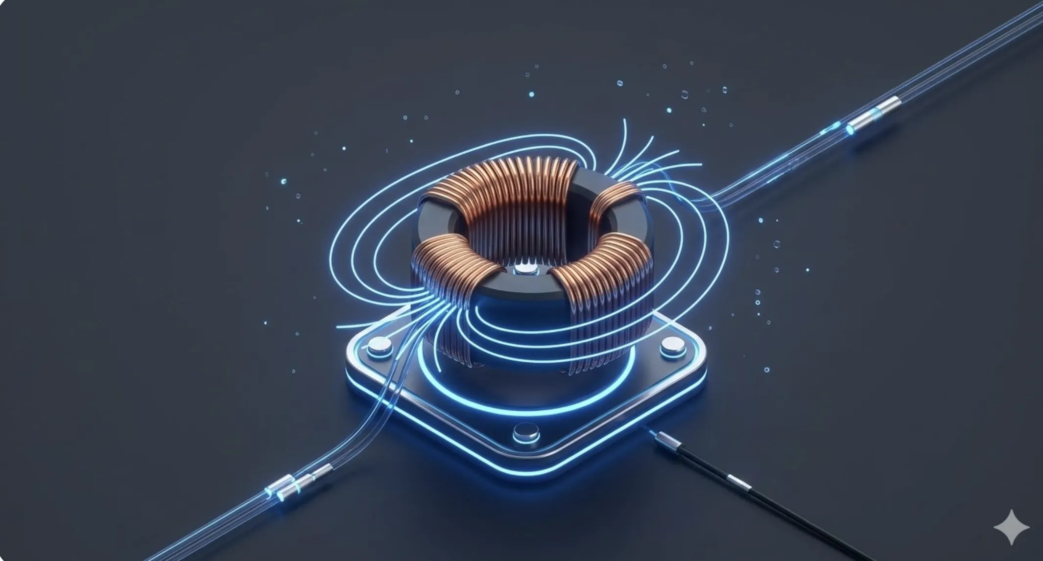
Step 3: Practical Application. By looping the data cable a couple of times through a toroidal ferrite core, we significantly increase the common-mode inductance. This is a standard engineering step to ensure Electromagnetic Compatibility (EMC) in professional electronic products.