The Electrolytic Capacitor: Technical Fundamentals
💡 Quick Tip
The electrolytic capacitor is an essential passive component designed to store high electrical energy densities in small volumes. Thanks to its construction based on a liquid or gel electrolyte, it achieves capacities far superior to ceramic models. Its use requires technical rigor: it is imperative to respect polarity and working voltage to avoid catastrophic failures. When designing filtering circuits, ESR (Equivalent Series Resistance) and operating temperature must be monitored, as heat degrades the internal chemistry, reducing its useful life and compromising the stability of the power supply in any professional electronic design.
Fundamentals of Electrolytic Capacitors
An electrolytic capacitor is a passive electronic component designed to store high amounts of electrical energy in a relatively small volume. Unlike ceramic or film capacitors, it utilizes a chemical electrolyte (liquid or gel) as one of its plates, enabling significantly higher capacitance values, ranging from microfarads (µF) to several Farads in the case of supercapacitors.
Internal Structure and Chemistry
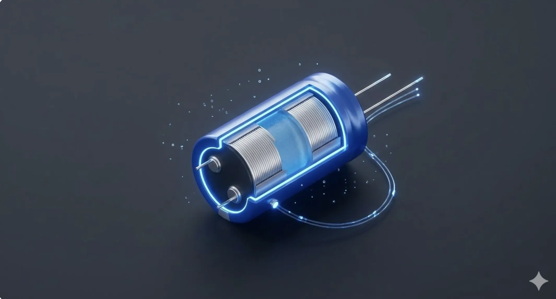
The construction consists of two aluminum foils, one coated with a microscopic layer of aluminum oxide which acts as the dielectric. The foils are separated by paper soaked in the electrolyte. Because the dielectric layer is extremely thin ($d$) and has a high permittivity, the capacitance $C = ε cdot (A / d)$ becomes massive compared to other capacitor technologies.
Key Technical Specifications
- Capacitance: Measured in Farads, defining the charge stored per unit of voltage.
- Rated Working Voltage (VDC): The maximum voltage the dielectric can withstand before breakdown. For reliability, it is best practice to select a capacitor with a 20-30% margin above the circuit's nominal voltage.
- Equivalent Series Resistance (ESR): This represents the internal resistance of the component. High ESR causes internal heating and efficiency loss, which is particularly critical in high-frequency Switching Mode Power Supplies (SMPS).
- Service Life: Electrolytic capacitors contain liquid which "dries out" over time, especially in high-temperature environments. This leads to a loss of capacitance and an increase in ESR, making them the leading cause of failure in aging electronic hardware.
📊 Practical Example
Real-World Scenario: Restoration and Improvement of Filtering in an Audio Switching Power Supply
You are repairing a high-fidelity audio amplifier that presents a persistent 50 Hz hum in the speakers and reboots unexpectedly under maximum load. After a visual inspection, you detect that the main electrolytic capacitors in the rectification stage are slightly bulged. This is a classic symptom of chemical fatigue and dehydration of the electrolyte, which increases the Equivalent Series Resistance (ESR) and reduces the component's energy storage capacity.
Step 1: Failure Analysis and Desoldering. We use an in-circuit ESR meter to confirm our suspicions. A healthy 4700µF capacitor should read less than 0.05$\Omega$, but the defective ones show values exceeding 2$\Omega$. This high internal resistance turns the filtered energy into heat, accelerating the degradation of the component. We proceed to desolder the components using a vacuum desoldering station to avoid damaging the copper traces of the double-layer board, which are sensitive to prolonged excess heat.
Step 2: Selection of Industrial-Grade Replacement. The original design used 4700µF / 25V capacitors at 85°C. To improve technical reliability, we decided to install replacements of the same capacitance but with a working voltage of 35V and a temperature rating of 105°C (Automotive or Industrial Grade). The higher nominal voltage means a more robust aluminum oxide dielectric, and the higher temperature ensures that the electrolyte does not evaporate prematurely in the closed environment of the amplifier chassis.
Step 3: Ripple Current Calculation. It is vital to verify that the new component supports the ripple current generated by the amplifier's consumption (approx. 3A peak). A common mistake is choosing a capacitor based only on µF and V, ignoring the Ripple Current. We select a 'Low ESR' high-current series, which uses etched aluminum foils with a larger surface area to minimize heat loss. This ensures that the DC voltage delivered to the power transistors is pure, eliminating background hum and improving bass transient response.
Step 4: Installation and Oscilloscope Verification. When installing the new components, we triple-check the polarity, as a reverse connection in a capacitor of this size would cause an explosion due to a sudden release of gases. After soldering, we power up the equipment with a variac and measure the ripple with the oscilloscope in AC mode. We observe that the noise has dropped from 1.5V peak-to-peak to less than 50mV. The amplifier regains its sonic clarity and thermal stability, extending its operational life for another decade thanks to a correct technical selection of passive components.